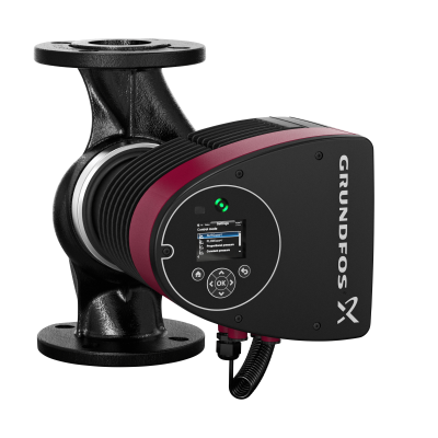
Question: How do I read the Magna date code and what is the warranty on them?
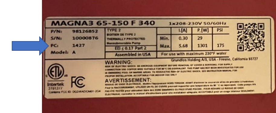
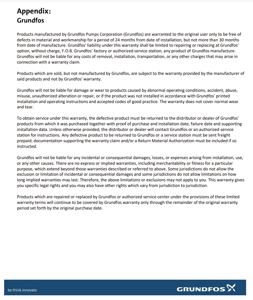
Answer: The production code is shown on the third line on the tag sticker which is located on the right side of the pump head. It goes by year and week of manufacture. For example, PC1427 was produced on the 27th week of 2014. The Grundfos Magna 3 warranty is 24 months from installation or 30 months from installation.
Question: I have a Magna 3 that I need to maintain a set temperature on a heat exchanger. What are my options?
Answer: There are two ways to configure on constant temperature mode based on where the pump is located. If it is on the return side after the heat exchanger, the internal sensor would maintain the temp and no external sensor would be required.
If on the supply side, an external combination pressure/temperature sensor (P/N 98404289) would be required to be connected to the analog input. To configure on the screen: Go to CONTROL MODE, select “Constant Temp”, under SETPOINT, input setpoint temperature, next go to SETTINGS and under Analog Input select “Function of analog input”, next “Constant temperature control”
When installing the sensor, the black wire is for temperature, power =brown, blue = ground and the grey unused wire is for pressure.
Question: How do I configure a 0-10 Amp signal from the building management system to control a Magna 3, 65-150 pump?

Answer: Under Settings, change control mode to Constant Curve
Go to Assist menu, arrow down to Setup, Analog Input press OK
Press (>) then select External Setpoint Influence, press OK
Select desired electrical signal (0-10V or 4-20mA), press OK then press (>)
Minimum – 0, Maximum -100
Under External setpoint function select either:
Linear with min. (linear with min. means that when the analog signal is at its lowest (0 volts or 4 mA), the pump will run at its minimum speed.
Linear with Stop (linear with stop means that when the analog signal is at its lowest (0 volts or 4 mA) the pump will be switched off
Then press (>) then OK.
Under Home, select Constant Curve.

Question: What is the fix for fault error code 77 for my dual head Magna 3 pump?

Answer: The fault code “77” refers to a communication error between the two pump heads. Check the second pump to verify that it has power or open the face plate and confirm that the molex connector (see below) for the power is securely plugged in.

Question: How do I troubleshoot a code “88” Magna fault code?
Answer: There are several steps to troubleshoot the code 88 and the 72 alarm. Use the steps below to resolve this issue:
Confirm that the sensor is plugged into the control box. You will need to disconnect main power and open the front cover of the pump to do this. If it was not plugged in, plug it in and run the pump and see if this took care of fault 88.

If fault still exists, make sure the sensor cable plug connections are secure and clean, and the sensor cable is installed correctly. Pay attention to the small pins in the sensor connector:

If there is still an issue, check the voltage across these terminals of the sensor cable (see below). If the reading is 0V, the cable is either not connected or damaged. Re-connect or replace the sensor cable (P/N 98700244) If the reading is between 4.65V and 4.88V, then it’s OK. If it is outside this range, then the entire control box needs to be replaced.

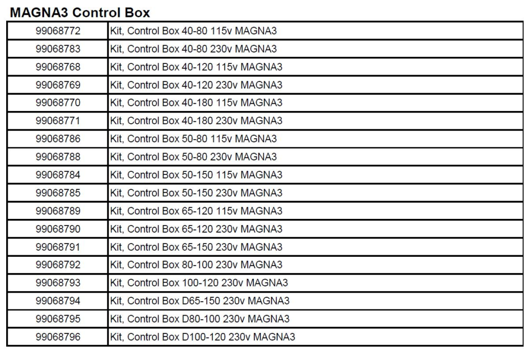
Below are the part numbers for replacing the control box. Please note that these will be a special order from your wholesaler.
If you’re still having an issue the, the sensor is likely plugged. Turn off power to the pump and drain it. Remove the sensor bracket and pull the sensor out of the pump housing. The hole, and the one on the opposite side (see pic below) should be clear, and slightly reflective. If the sensor holes are plugged with debris, or you can see through to the other side, the sensor needs to be replaced with part number 98471249 or pull out the rubber cap and carefully clean.

If the fault still exists, confirm correct cap is being used – see below. New cap is 7/8″ long, old cap is 5/8″ long. The new cap is sold as a service kit (P/N 98708139, qty of 10). Sensor cap should be re-inserted “nose down” see (see pic below).


are clear of any debris. Make sure to remove the sensor first, then run a wire from the inside hole of the volute to remove ant debris. To remedy any future debris issues, install a Spirotherm VDT series combination air and dirt eliminator.

Question: What do the colored lights on the Magna Screen refer to?
Answer: Each color and rotation provide status information at a quick glance. It is helpful especially helpful when the pumps are piped high up in the ceilings. Aside from the Magna series, this feature is now on the newly expanding ECM pumps up to 15 HP such as the CRE, CRE-DP, VLSE and CMBE series. Below is the reference Grundfos “eye chart” that explains specifically what each display means:

Question: I have a dual head Magna 3, model 65-150D that is mounted vertically and its sounds like it has air trapped in the top head. There is not a purge screw like the older large three speed UPS pumps.
Answer: The dual-head pumps installed in horizontal pipes can be fitted with an automatic vent, Rp 1/4″ thread, in the upper part of the pump housing if no venting valve is installed in the system. For more information refer to the installation and operations manual located under this Magna3 section.

Question: Can a Magna 3 be set for a minimum flow rate?
Answer: At this time there is no minimal setting available. However, it does have a maximum flow option in the latest “D” series models. Once set in this mode, a GPM setpoint will maintain the flow up to the maximum desired. This uses the calculated flow rate only, so it will not connect to an external flow sensor in this case.

Question: How do I update my Grundfos bluetooth dongle?
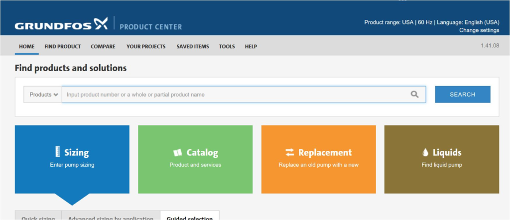
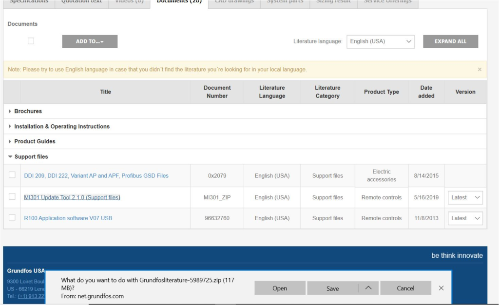
Answer: To update the dongle, follow the directions below while logged on to https://product-selection.grundfos.com/front-page.html?qcid=505831171

Below are the step-by-step instructions for the upgrade:
- Connect remote with a micro USB cord and type part number “98046408” in search window.

Question: What is happening to the pump during a fault code 29 forced pumping warning?
Answer: This warning is triggered by having unwanted or forced flow from other sources through the pump. This is caused by either not having a check valve or defective one causing back feed. I have also seen backflow from redundant pumps causing a non-powered Magna to show a low voltage fault due to the unwanted flow turning the pump into a generator.
Question: What do the Magna model numbers refer to?
Answer: The model numbers (or material numbers) as Grundfos refers to represent the inlet/outlet diameter and the head ability in metric. For example, the Magna 3 65-120 has a 50mm (1.96″) diameter and the head is 120 meters (36′ TDH).

Below is a conversion chart:

Question: Can the Magna 3 models accept either an external pressure sensor for differential pressure control or a temperature sensor for BTU monitoring applications?
Answer: Yes, Grundfos offers a combination pressure and temperature sensor that measures from 0-232 psi (0-16 bar) and 14 – 248 F (-10 to 120 C ). It is a type RPI T2 and the P/N is 98355521. It is good for BTU monitoring but not fully accurate for billing purposes.

The output is a 0-10 signal that gets connected to the analog input signal as shown below. Please note that the Magna 3 series has only one analog input. The length options for the screened cable is the 6.5′, P/N 98374260 or the 16.4′ which is P/N 98374271.

The next step would be to set it up on the control screen by going to the main menu tab ASSIST, choose “Setup, Analog Input”, select your function option, (ie: Differential pressure-control), “0-10”, “Linear with Min” and it is complete.
Question: I have a Magna 3 that often surges and cannot figure out what is the cause?

Answer: The most common reason for a Magna surging is due to the pump being incorrectly wired. Check to see if the power is being cycled on and off. As shown in the diagram below, the motor is to be continuously powered and enabled to run through the digital input.

If the wiring is not the issue, check to see that the system has enough pressure to run the pump. Another factor is to verify that each pump has a check valve on the discharge. If not, the surging pump could be receiving flow from the redundant one. If none of these solutions work, contact your local Grundfos wholesaler for additional troubleshooting support.
Question: Can just the Magna pump head be replaced?

Answer: Yes, all of the Magna 3 pump heads can be ordered per the Grundfos part numbers below.

Below is a picture of the kit that Dave Benham of Urell shared to show what is included: pump head, shaft, impeller and the O-ring.

Question: On a Magna 3, do I install a BACNet CIM card in the master pump or both?

Answer: It depends on which model. If it is a single head Magna 3, both require CIM cards to communicate back to the BMS. For the dual head Magna 3D models, the older (pre-2018) series needs a card in each head. For the latest dual head “D” series, only in the master head.
See below for CIM/CIU and Multi-pump applications for more details.


Question: I am having difficulties having a set of Magna 3 pumps connect for alternating control. Getting a fault code (77) when I pair them through their Bluetooth connection. Never had this happen before, any suggestions?

Answer: If you are familiar with setting up lead-lag control and your having the communication fault code “77”, it is most likely one is an “A” series and the other a newer “D” series. (This can be verified by checking the name plate located on the right side of the pump head as you are facing it.) Both Magna’s need to be the same series to talk to each other.

The fix is to go from home over to the settings tab, then scroll down to bus communication, then multi-pump profile selection. Select the A,B,C compatibility option and then go through the normal assisted multi-pump set up.

Question: How do I wire a single-phase Magna 3 to the available three phase?
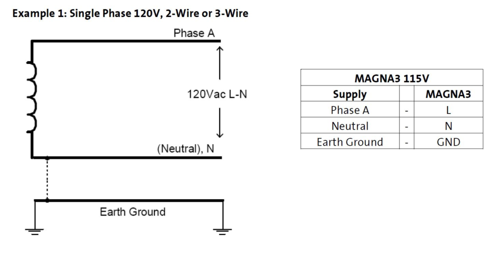
Answer: The Magna 3 accepts a single-phase power input; however, it is common in many installations to replace an existing three-phase pump with the Magna 3 by simply using two “hot legs” and ground to provide the appropriate supply voltage to the pump. Any remaining unused power supply legs are disconnected from the panel and both ends are tied off and marked appropriately.

The Magna 3 is available in two voltage variants: Single Phase 115V and Single Phase 208-230V. Always check the nameplate to verify the voltage rating of the pump before connecting power.
The following examples show the Magna 3 can be connected to power in differing supply configurations. If there is any uncertainty regarding the existing configuration a qualified person can measure the supply voltage with an AC voltmeter to ensure the correct legs are used to deliver the appropriate voltage to the pump.
NOTE: Electrical connections and protection must be done by qualified personnel in accordance with local regulations and the MAGNA3 Installation and Operating Instructions:


Question: What flange kits fit the multiple Magna models?
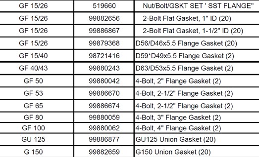
Answer: Below is a list of both the cast iron and bronze Magna flange kits:


Below are the corresponding gasket kits for the flange kits:
Question: Can I set up start/stop on a Magna 3 through a BACnet CIM card rather than hard wire directly to the pump?
Answer: Yes, the Binary Outputs can be changed to allow Bus on and off control. The BO, 0 sets the control source. Set to “1” to enable control via BUS Control and Local control is factory default at “0”.

Below is the complete list of binary outputs on the BACnet CIU300 part number 96893769:


Question: How do I create an analysis report on a Magna 3 using the Bluetooth Grundfos Go remote?
Answer: Once connected, go to the “Reports” button on the bottom of the app and the window below will open up. Name the project, take three pictures- pump head, motor tag and the pump head ID tag. After completed, it will automatically save and can be emailed out. Below is a sample of the report.
Question: How accurate is the GPM readout on the Magna display?

Answer: For most applications, it is accurate to the actual flow. However, if the duty point is far to the left or right of the pump curve, it will diminish. In this case, there can be a 5%-10% differential between actual flow. In a dual head Magna 3, the right side can be up to 12%. Below is a chart supplied by Grundfos that illustrates the different models.

Question: I run a housing development and want to set up Magna’s for estimating (non-billable) BTU monitoring.
Answer: Yes, it can be in Differential Temperature control mode. The pump should piped on the supply side using the built in sensor. It is accomplished by adding an external Magna 3 Delta T temperature sensor on the return side, (P/N 98477669). It includes a six foot 4-wire AWG22 cable which is to be connected to the analog input shown below.


Go to SETTINGS, drop down to ANALOG INPUT and select the sensors parameters of 0-10V or 4-20 mA . Note that each pump must have its own sensor even if connected in a lead-lag control. If needed, the 6′ cable can be extended with a 22 gauge shielded cable. The last step is to go to the home screen and add the differential temperature for the setpoint.

Question: How do I set up a Magna 3 to communicate with BACNet controls to my building automation system?
Answer You will simply need to add a Grundfos BACnet CIM (Communications Interface Module) P/N 96893770. In New England, most of the wholesalers such as Blodgett Supply, F W Webb and The Granite Group stock them. There is an instructional step by step video under the video menu above.

The CIM 300 is a standard interface for data transmission between a BACnet MS/TP network and a Grundfos pump or controller. It makes data exchange possible between Grundfos pumping systems and a Building Management System or a supervisory controller.
The communication interface is based on standard BACnet object types, allowing for straight forward data access over the network. The functional profile has been optimized for exchanging data between pumping systems and building management systems / operator workstations.
The CIM 300 is an add-on communication module installed internally in the Grundfos product with transmission speeds (BACnet): 9.6 / 19.2 / 38.4 / 76.8 kbps. In addition to BACnet MS/TP, interface modules are also available for GENIbus, LON, Modbus RTU, Modbus TCP, PROFINET IO, Profibus, GSM/GPRS (wireless communication) and GRM.

Question: The insulation jackets that came with the Magna 3 pumps were accidentally thrown out. My wholesaler is having trouble figuring out the part numbers?
Answer: Below is the Magna 3 series insulation covers part numbers.
- P/N 98827415 – MAGNA 3, 40-XXX
- P/N 98827416 – MAGNA 3, 50-XXX
- P/N 98827417 – MAGNA 3, 65-XXX
- P/N 98827418 – MAGNA 3, 80- XXX
- P/N 98827419 – MAGNA 3, 100-120- XXX

Question: What control settings are recommended for typical HVAC systems?
Answer: There are several options depending on the application. For example, the Magna 3 is set in default in AutoAdapt (self-optimization) control mode. This is applicable for about 80% of system heating applications as long as the pump was duty point was selected to be within the specific curve. For example, this Magna 3 below must be operating in the blue shaded area within the curve to satisfy the demand.
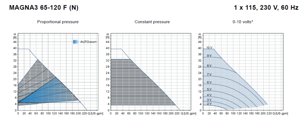
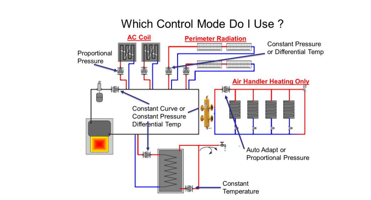
If the actual demand is a high head/low flow or high flow/low head, it needs to be changed to proportional pressure that offers a wider range. Once set to proportional pressure, make the setpoint the highest head pressure required. The pump will adjust itself from that point to 50% of it automatically as valves open and close. Most facility HVAC techs I work with occasionally adjust down the setpoint until they can maintain the demand at its lowest most efficient set point.
Below are the setting options and recommendations for multiple system applications.
AUTOADAPT – Continuously adapts the pump performance according to the actual system characteristic
FLOWADAPT – The pump will run AUTOADAPT and ensure that the flow never exceeds the entered FLOWLIMIT value.
PROPORTIONAL PRESSURE – The pump head is reduced at decreasing water demand and increased at rising water demand.
CONSTANT PRESSURE – The pump maintains a constant pressure, irrespective of water demand.
CONSTANT TEMPERATURE – This control mode ensures a constant temperature.
DIFFERENTIAL TEMPERATURE – This control mode ensures a constant differential temperature drop across a heating system.
CONSTANT CURVE – The pump can be set to operate according to a constant curve, like an uncontrolled pump.
For additional information, contact your Grundfos wholesaler or rep agency.
Question: Are Magna’s now being used to create variable speed boiler loops?
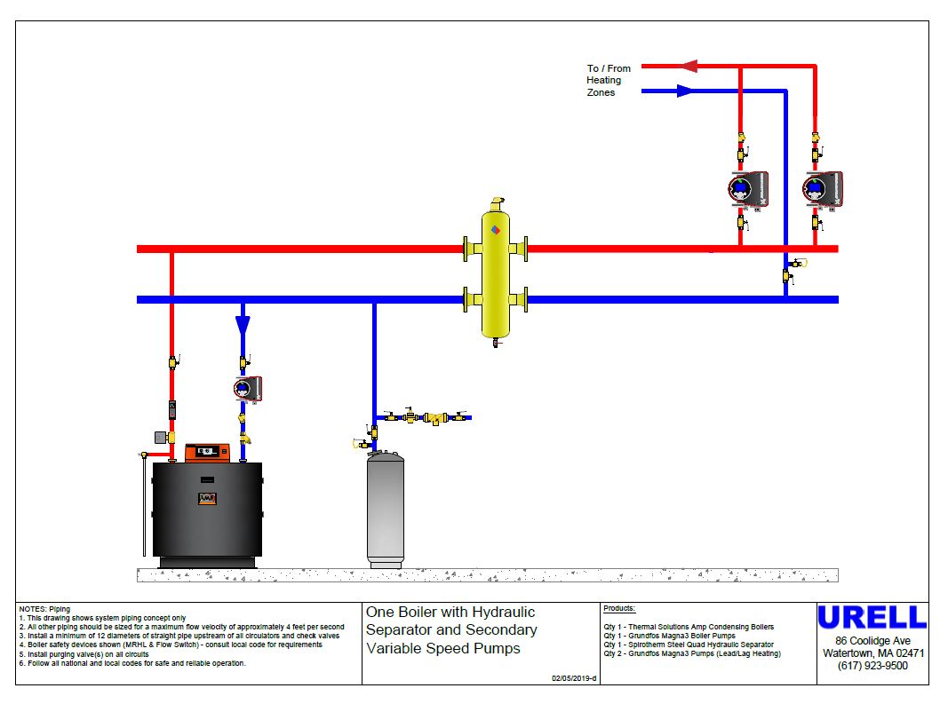
Answer: Grundfos and Thermal Solutions, the commercial condensing division of Burnham Holdings has partnered by incorporating Magna 3 circulators to their control logic. In short, the “Eco-Propel” controls allow the boiler to communicate with the pump to adjust to the systems demands. By doing so, the boiler can attain the required delta T to condense.
In more detail, the Magna 3 Eco-Propel Variable Speed Pump Magna 3 Kit is pre-engineered to integrate with boiler firing rate control ensuring efficient temperature control while maximizing electrical energy savings. Boiler pump speed demand is calculated based on supply and return temperatures, and boiler firing rate. All you have to do is dial in the desired setpoint.
Heating systems are designed for a specific differential temperature or delta T across supply and return temperature. Standard fixed speed boiler pump systems allow the differential temperature to change as the boiler load changes. For example, as the boiler firing rate modulates from high to low fire standard fixed speed boiler pumps over pump and cause system differential temperature to drop.
Eco-Propel continuously adjusts pump speed to maintain a constant differential temperature as the boiler firing rate modulates. The result lower return temperature boosting efficiency and minimized electrical usage. The Eco-propel system provides the following benefits:
Matches Boiler Pump to Boiler: Boiler pumps are generally oversized. The Eco-propel kit is factory tuned to produce an optimized match of boiler pump to boiler and piping. Energy is saved by preventing over pumping over the full modulation range.
Helps Increase Boiler Efficiency: Standard constant speed boiler pumps allow return temperature to increase as firing rate is reduced. This is due to the excessive water flow rate across the boiler. Eco-Propel decreases pump speed as the firing rate decreases helping to maintain more efficient, lower return temperatures.


Below are pre-engineered Eco-Propel APEX series boiler designs (425-825 MBH) from that include the boilers, Magna 3 series and Spirotherm Quad combination hydraulic separators/air & dirt eliminators.
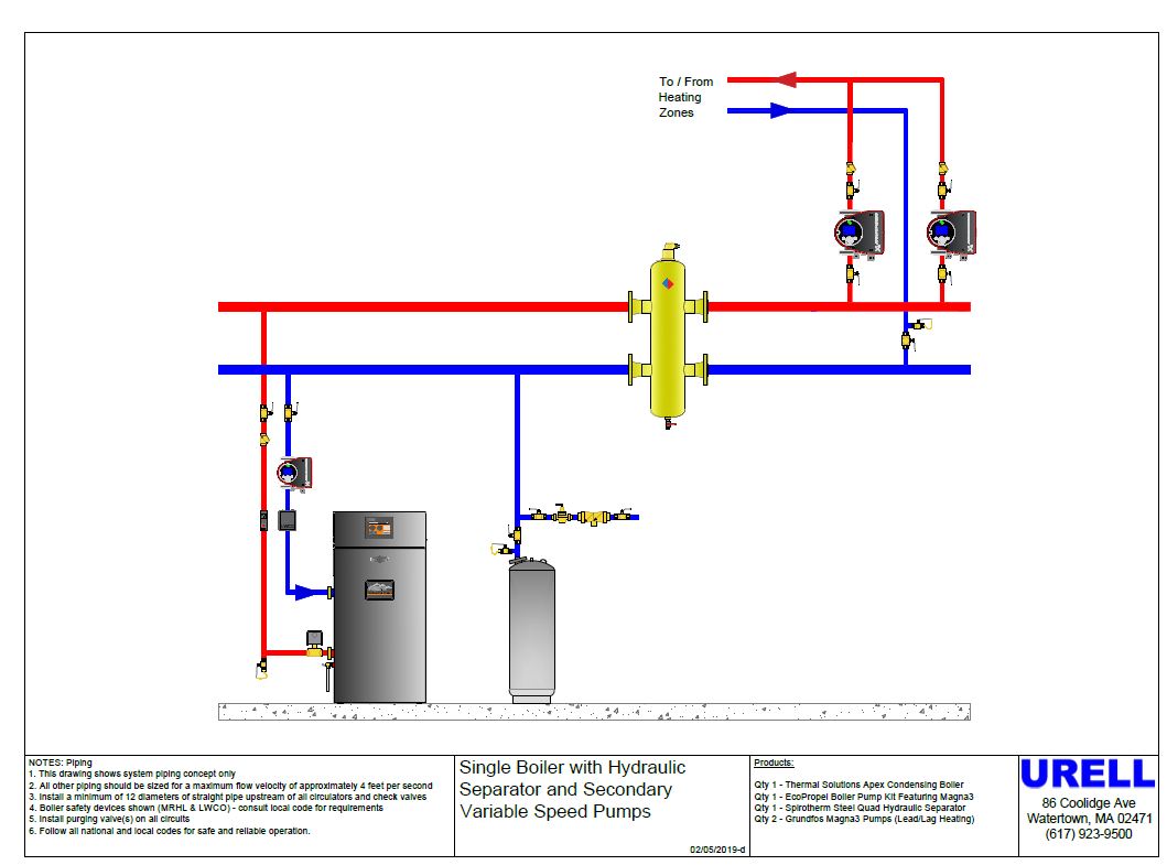
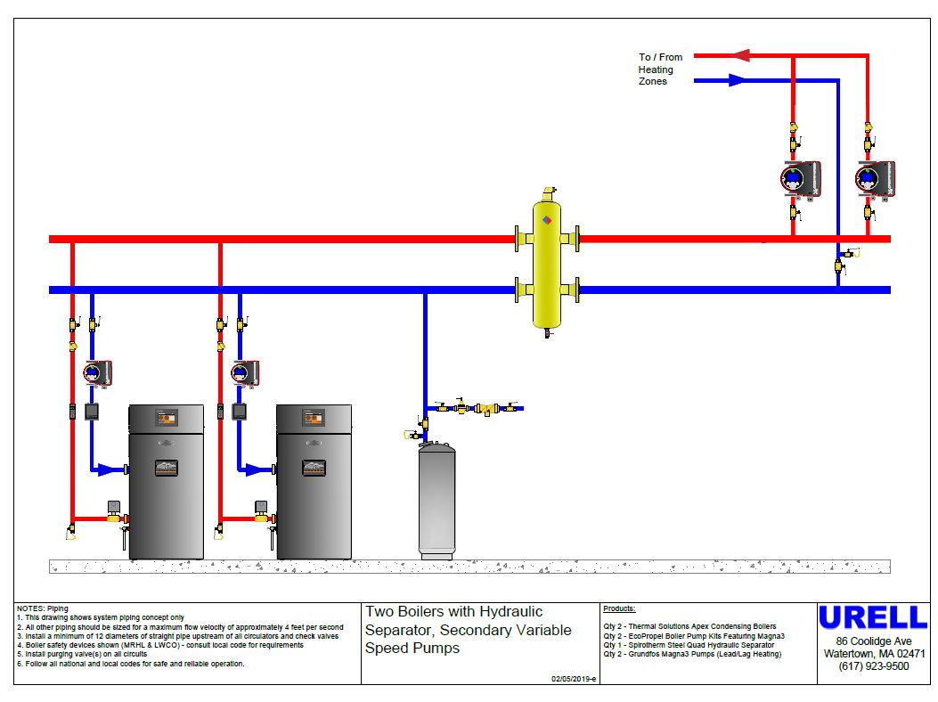
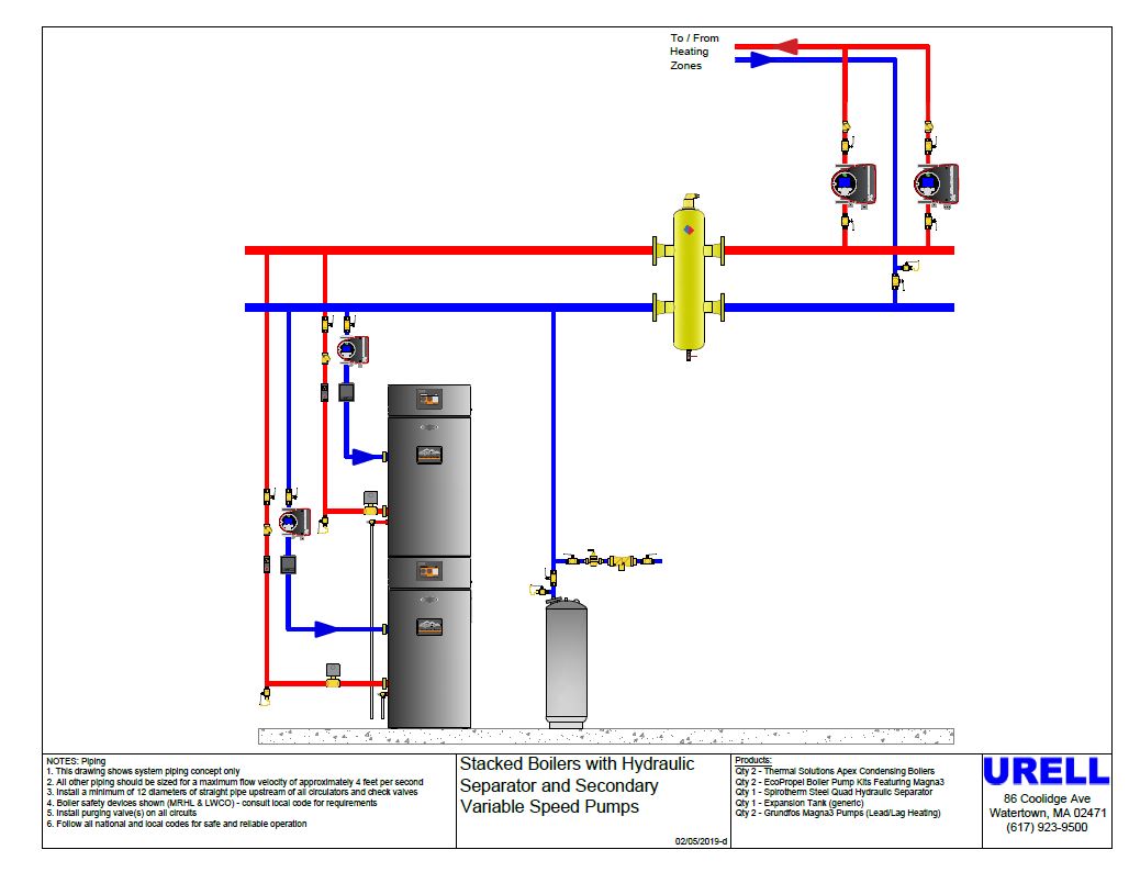
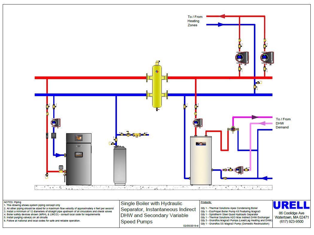
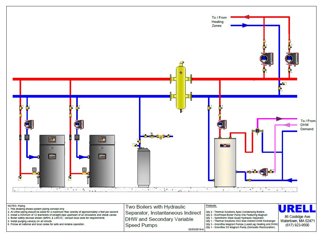

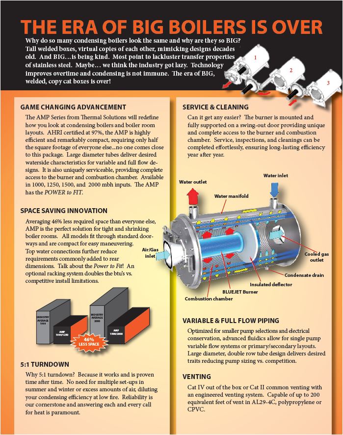

Below are pre-engineered Eco-Propel AMP series boiler designs (1000-4000 MBH) designs from that include the boilers, Magna 3 series and Spirotherm Quad combination hydraulic separators/air & dirt eliminators.
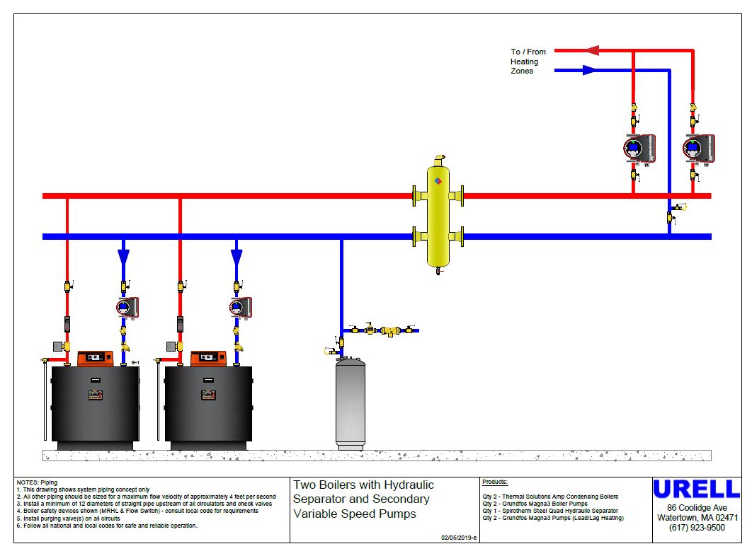
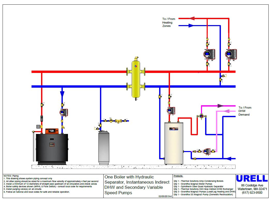
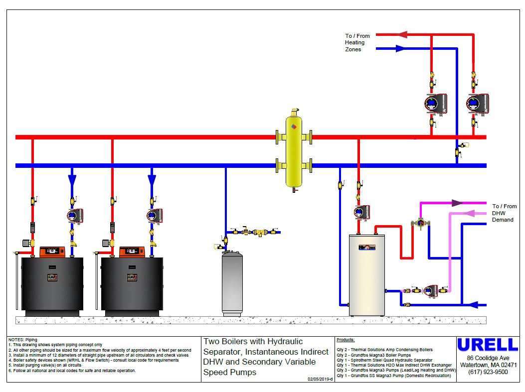
For additional information on Eco-Propel or Magna 3 series, please contact your local wholesaler or rep agency.
Question: I need to replace the external sensor on a Magna 3, can I fix it and how do I replace it?
Yes, the replacement P/N is 98471249 and is available in most supply houses. After the pump has been isolated, remove the stainless-steel ground screw and slide back the support clamp that is fitted in the grooved rails.
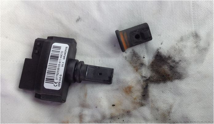
Next gently pull out the sensor and be sure to remove the rubber boot that covers the sensor that often stays stuck in the hole. Next open up the supply valve and blast fresh water through to clear out any last debris. Clean both the sensor and rubber boot and verify that there are no dirt particles or magnetite in the two sensor eyes or built up inside the boot.
Do not under any circumstances use any metal cleaning tools because it will damage the glass inside and wreck the sensor. Once completed, reinstall with the “bump”side on the sensor boot facing away from the volute. You will know if you installed it backwards because the pump head screen will not light up.
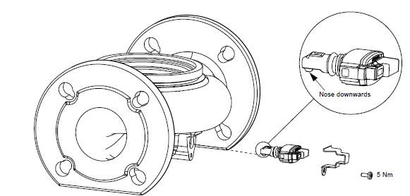
After the ground screw and clamp is securely fastened, slowly open up the supply to check for leaks. Now you are done.
If the problem re-appears, then it is a usually a system water quality issue. A Spirotherm VDT air/dirt eliminator unit will clean up the system. Once it is in place, run the pump at maximum setting periodically to allow the debris to come out of suspension and use the purge valve to keep blowing it down in a clean white bucket until the water looks clear.
The replacement sensor kit that includes the sensor wire cable, mounting bracket and screw as P/N 98471249.
Good luck!
Question: Are Magna’s now being used to create variable speed boiler loops?
Answer: Yes, Grundfos and Thermal Solutions, the commercial condensing division of Burnham Holdings has partnered by incorporating Magna 3 circulators to their control logic. In short, the “Eco-Propel” controls allow the boiler to communicate with the pump to adjust to the systems demands. By doing so, the boiler can attain the required delta T to condense.
In more detail, the Magna 3 Eco-Propel Variable Speed Pump Kit is pre-engineered to integrate with boiler firing rate control ensuring efficient temperature control while maximizing electrical energy savings. Boiler pump speed demand is calculated based on supply and return temperatures, and boiler firing rate. All you have to do is dial in the desired setpoint.

Heating systems are designed for a specific differential temperature or delta T across supply and return temperature. Standard fixed speed boiler pump systems allow the differential temperature to change as the boiler load changes. For example, as the boiler firing rate modulates from high to low fire standard fixed speed boiler pumps over pump and cause system differential temperature to drop.
Eco-Propel continuously adjusts pump speed to maintain a constant differential temperature as the boiler firing rate modulates. The result lower return temperature boosting efficiency and minimized electrical usage. The Eco-propel system provides the following benefits:
Matches Boiler Pump to Boiler: Boiler pumps are generally oversized. The Eco-propel kit is factory tuned to produce an optimized match of boiler pump to boiler and piping. Energy is saved by preventing over pumping over the full modulation range.
Helps Increase Boiler Efficiency: Standard constant speed boiler pumps allow return temperature to increase as firing rate is reduced. This is due to the excessive water flow rate across the boiler. Eco-Propel decreases pump speed as the firing rate decreases helping to maintain more efficient, lower return temperatures.


Below are pre-engineered Eco-Propel APEX series boiler designs (425-825 MBH) from that include the boilers, Magna 3 series and Spirotherm Quad combination hydraulic separators/air & dirt eliminators.


Below are pre-engineered Eco-Propel AMP series boiler designs (1000-4000 MBH) designs from that include the boilers, Magna 3 series and Spirotherm Quad combination hydraulic separators/air & dirt eliminators.


For additional information on Eco-Propel or Magna 3 series, please contact your local wholesaler or rep agency.
Question: Can set up Magna’s in alternating without the cost and labor of adding a Tekmar device?
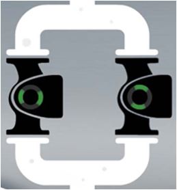
Answer: Yes. Built in is a Grundfos proprietary wireless signal called “GenieAir” (similar to a Bluetooth frequency) that allows the pumps to communicate between each other. This is commonly used when there is no BMS and they are “stand alone” redundant pumps.
To activate, hit the HOME screen first to start with a fresh screen. Next scroll up to the fourth menu button tab to ASSIST, press OK and scroll down to MULTI-PUMP function. press OK and select ALTERNATING OPERATION. Press OK and select TIME BASED then press the right arrow button to have the primary pump hunt for the redundant pump.
Once the GenieAir blue line shows up on the screen, press the OK button on the redundant pump and soon will list it on the primary pump screen to which you will press OK. Now your done. It will confirm on the screen that the set up configuration is complete.
Just a tip that I set my pumps consistently to 9:00 AM. The rationale is that if the building owner wants to see it change over, he can have his coffee and verify the changeover at a reasonable time that’s easy to remember.
Another way to test on the spot is simply to turn off the power on the running pump and see them alternate. When you see the yellow warning “communication error” on the screen, don’t worry, it’s just letting you know that the other pump has lost power. Once it is re-energized, the pump logic will reset the alarm automatically.


