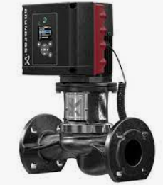
Question: How do I set up a TPE3 in alternating control?
Answer: The Grundfos built MLE motors have the option of being connected either by Bluetooth or wired for multi-pump alternating control mode through an AYB. Below are the instructions for hard wiring:
Electrical Connections for Multi Pump
Remove the jumper (terminals 2 & 6), because we will use the digital input 1 as an external start-stop.
Terminal Function
2 Digital Input 1
6 Ground
The multi pump system is to be controlled by an external start/stop switch as shown below:
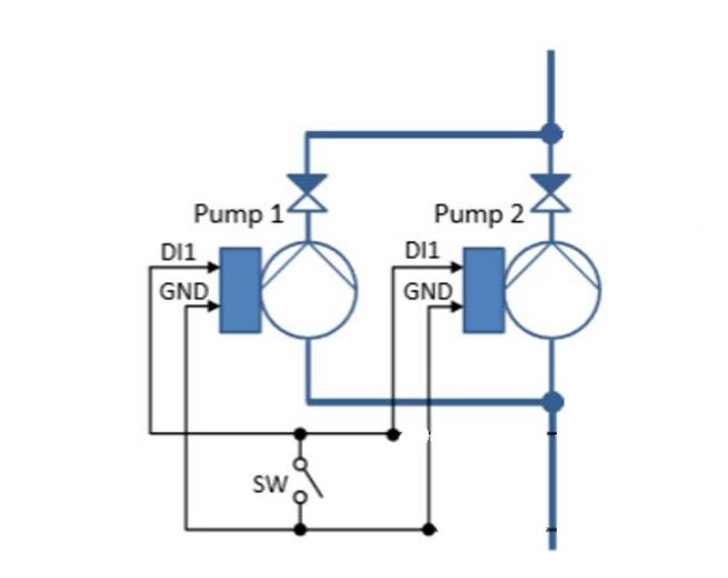
The Digital Input 1 (terminal #2) terminals are to be wired together.
The Ground (terminal #6) terminals are to be wired together. (Must be #6 on both pumps)
The Switch (SW) is to be placed across these two wires.
The external switch (SW) will start the complete system, no matter which pump has the master role.
The digital input 1 on both of the pumps in the system is to be set to “Ext stop”. The factory setting of digital input 1 is “Ext stop”. The switch (SW) is to be closed for the pumps to run.
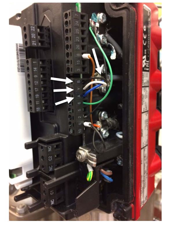
Connect the AYB terminals of pump number 1 to the AYB terminals of pump number 2. Use a screened cable between the GENIbus terminals. Connect the screen of the cable to the frame.
Multi Pump Function
The multi pump function enables the control of two pumps connected in parallel without the use of external controllers. The pumps in a multi pump system communicate with each other via the wireless GENIair connection or via the wired GENI connection.
Three different multi pump functions are available:
• Alternating operation, time
• Alternating operation, energy
• Back-up operation
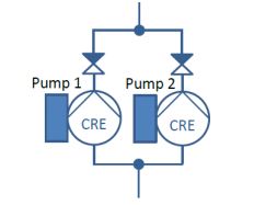
Alternating operation functions as a duty/standby operating mode with only one pump in operation at a time. Alternating operation is possible with two pumps of the same size, type, and connected in parallel.
Any pump can function as the master pump and take over the master pump function if the master pump should fail. This is only possible if each pump is configured with a discharge pressure sensor.
Installation – Confirm
Each pump requires a non-return valve in series with the pump.
Enable the Multi Pump Function
The main purpose of the multi pump function is to ensure an even amount of running hours and to ensure that the standby pump takes over if the running pump stops due to an alarm.
The operating pump can be altered based on time or load. The time based alternation takes place when the duty pump has been running for 24 hours. The load based alternation takes place when the duty pump has consumed 20kWh.
Give the first pump the pump number “1” using the graphical control panel
Home menu
Settings menu
Communication OK
Pump number OK
OK (change to Pump 1) OK
Home menu
Give the second pump the pump number “2” using the graphical control panel
Home menu
Settings menu
Communication OK
Pump number OK
OK (change to Pump 2) OK
Home menu
Go to the “setup of the multi-pump system” using pump number 1.
Home menu
Assist
Setup of the multi-pump system OK
>
Wired GENIbus OK > (Select the communication channel)
>
Alternating operation, energy OK > (Select the multi-pump function)
OK (Search for other pumps)
OK > (Pump 2 winks)
(See * below)
OK (Confirm the setting)
- The pump changeover will be made automatically when the difference in energy consumption of the two pump is equal to the daily energy consumption of one pump running at the rated performance.
Below is the graphical control panel displays for the two pumps.
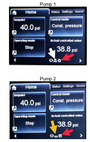
- The symbol at the end of the white arrow indicates master pump.
The symbol at the end of the yellow arrow indicates slave pump.
The symbol at the end of the red arrows indicates the pumps are turned off by the start/stop button.
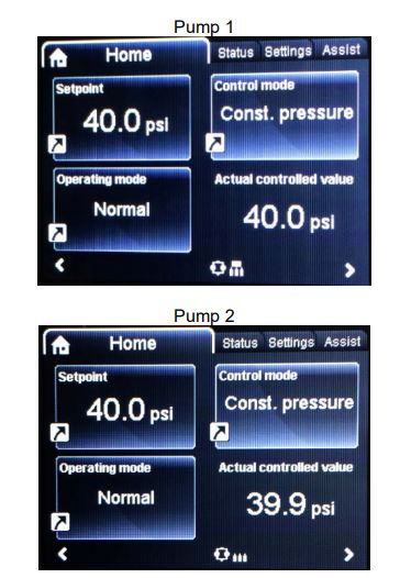
Operate the pumps in the multi-pump mode by pressing the start stop button on pump one and then press the start stop button on pump 2.
Pump 1 operates, and pump 2 is in standby mode.
The graphical displays of pump 1 and pump 2 look as follows:
- If alternating operation – time is selected, the operating pump must run continually for 24 hours before the standby pump is switched on. If the pump is switched off in the 24 hour period, the 24 hour clock restarts.
Deactivate the multi-pump function.
Go to the setup of the multi-pump system using the master pump. (Pump 1)
Home menu
Assist
Setup of the multi-pump system OK
OK > (Deactivates)
OK
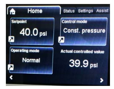
The graphical displays of pump 1 and pump 2 look as follows:
For additional support, contact your local Grundfos rep agency or supply house.
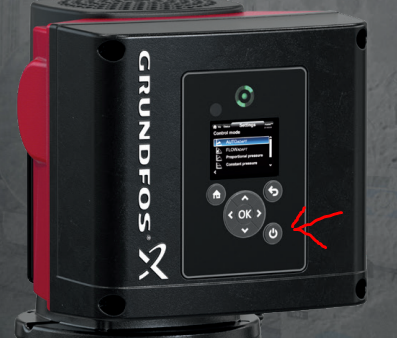
Question: I removed the cover off a new TPE 3 just like I have done with Magna’s and now I cannot get the pump to turn on?
Answer: The TPE3’s have a new feature which is an on/off button on the bottom right of the faceplate. If the faceplate is removed, it goes unnoticed.
Question: Can I add differential temperature control mode to a TPE3?
Answer: Yes, the best solution is to use the Grundfos RPI+T sensor which does both differential pressure and temperature all in one unit. This would be installed to the analog input in the VFD. It is Grundfos part number 98477669 and has a 1/2″ NPT connector.
Question: I removed the cover off a new TPE 3 just like I have done with Magna’s and now I cannot get the pump to turn on?
Answer: The TPE3’s have a new feature which is an on/off button on the bottom right of the faceplate. If the faceplate is removed, it goes unnoticed.


