
To be fair to Balancing Contractors, the first time they get onsite and see a Grundfos Magna 3 pump, it can be intimidating. they are very different than standard three piece designed pumps. However, they are the future as energy costs rise.
For years, the trades have worked with the same pumps with no integrated controls, DP sensors or VFDs. The good news is that the balancing process is not that difficult. To the best of my knowledge, Grundfos or any other any of the pump manufactures unfortunately have not published any instructions on how to balance these types of pumps.
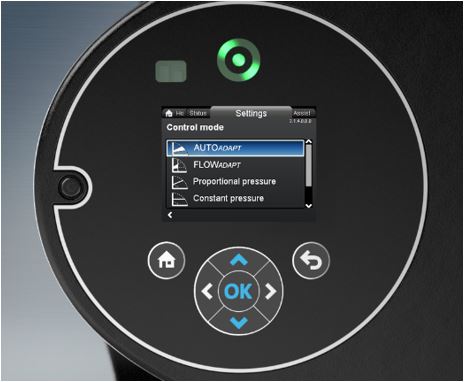
The Magna 3 series screen displays the flow in GMP that makes the balancing process painless. This procedure also is the same for the new *MLE motors up to 15 HP (TPE3,CRE, CRE-DP, VLSE) that have (ECM) permanent magnet motors.
DIRECTIONS to balance a system with mostly 2-way control valves, and manual balancing valves (circuit setters):.
The zone with the highest calculated pressure drop should be noted and indicated to the balancer (the balance valve on this zone should end up being 100% open). Once the system has been filled, cleaned, and flushed, follow the steps below:
- Set the pump in Constant Curve mode.
- Open up all the balancing valves to 100%
The system should be balanced conventionally using the pumps manual adjustment like a VFD. Once the system is balanced with all valves open the pumps parameters should be recorded. RPM, GPM if available and differential pressure.
Next, change operating mode to Proportional Pressure. (All control valves should still be open.)
- Adjust the proportional pressure speed until the previously recorded parameters are met. (As valves modulate closed the pump will slow down.)
The last step is to CLOSE all control valves with the exception of the zone with the highest calculated pressure drop. Let the pump speed equalize (this may take several minutes). Verify that you have flow in that zone.
If you do, the previously selected set point is correct, and the system is balanced in proportional pressure. If you do not have enough flow, simply increase the proportional pressure setpoint until you do. Once that has been confirmed the system is balanced in proportional pressure.
DIRECTIONS to balance a system designed with 2-way pressure independent control valves. (ie: Danfoss ABQM or standard 2-way control valves and autoflow balance valves.)
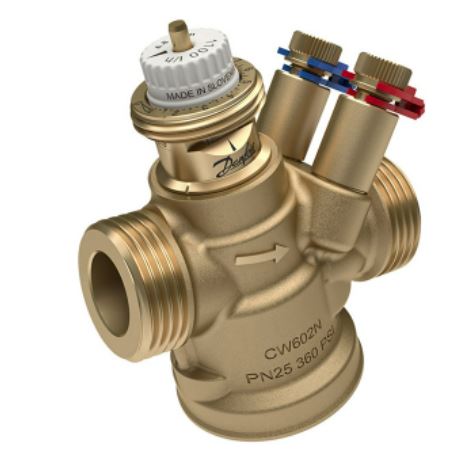
Using an ultrasonic flow meter is the best way to read the flow at the pump. The zone with the highest calculated pressure drop should be noted and indicated to the balancer. Autoflow valves with a 2-psi min differential are preferred over units with 5 psi min differential.
Once the system has been filled, cleaned, and flushed, proceed with the following steps:
- Set the pump in constant curve mode.
- All control valves should be commended open.
- Set the pump speed to 100%.
As long as the inlet pressure on all valves or autoflows is below the max the valves will regulate the flow. The flow at the pump should match the design flow. If the flow at the pump is higher than the design one, or more of the valves or autoflows are seeing an inlet pressure above their rating and they are overflowing.
- Slow the pump to 90% speed. If the flow has not dropped below the design flow all of the valves or autoflows are still seeing an inlet pressure above the minimum.
Continue to slow the pump speed until the flow at the pump drops below the design. When this happens, you know that one or more of the valves or autoflows is seeing an inlet pressure below the min.
Increase the speed until you have reached design flow and record the parameters. RPM, GPM, and differential pressure.
- Change the pumps operating mode to Proportional Pressure. (All of the control valves should remain open.)
- Adjust the proportional pressure speed until the previously recorded parameters are met. (Now, as valves start to close the pump will slow down.)
Lastly, close all control valves with the exception of the zone with the highest calculated pressure drop. Let the pump speed equalize (this may take several minutes). Verify that you have the desired flow/inlet pressure. If you do, the previously selected set point is correct and the system is balanced in proportional pressure.
If you do not have enough flow increase the proportional pressure setpoint until the desired GPM is reached. Once that has been confirmed the system is balanced in Proportional Pressure.
* Tip: On the older asynchronous MLE motors (pre 2018), use Constant Curve control mode, set the speed to 100% and read the differential pressure across the pump you can plot that point on the pump curve. Then you know the full speed flow in GPM. The full speed pump rpm is +/- 3500. From there if you slow the pump down you can calculate the flow using the pump laws. GPM is directly proportional to RPM. RPM1/RPM2 =GPM1/GPM2.
For those in New England, Urell represents Danfoss pressure (https://www.danfoss.com/en/products/valves/dhs/hydronic-balancing-and-control/pressure-independent-balancing-control-valves-pibcv) independent control valves (PICV’s) which combined with Grundfos E-Solutions and Spirotherm (http://www.spirotherm.com/products/combination-air-dirt ) air/dirt elimination VDT series you will have the most efficient and comfortable hydronic HVAC system available.